.png)
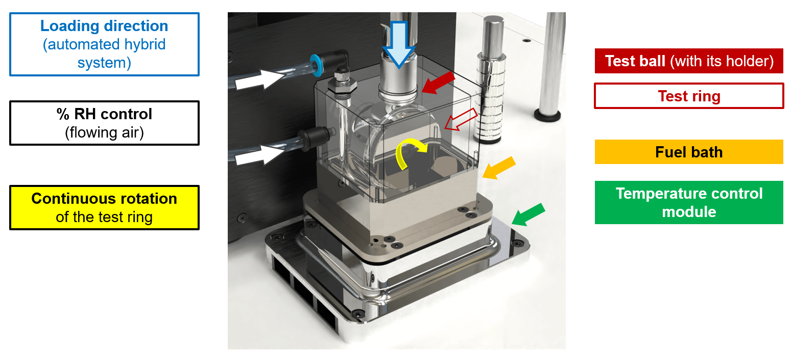
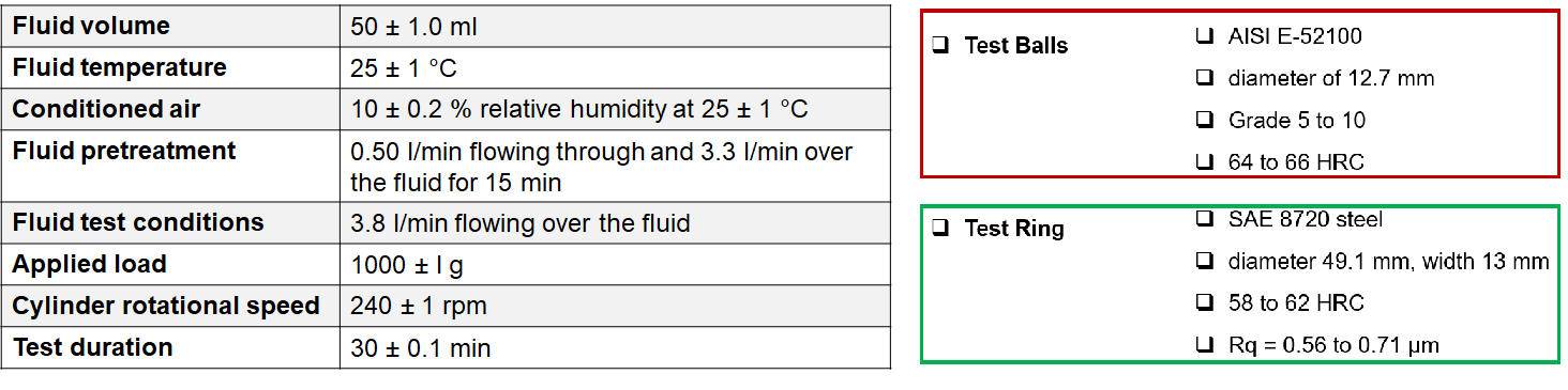
The BOCLE test, is designed to assess wear characteristics of aviation turbine fuels on rubbing steel surfaces as per ASTM D5001. The fluid under test is placed in a test reservoir in which conditioned air at 10 % relative humidity flows during the test. A non-rotating steel ball is loaded against the outside diameter of an axially mounted cylindrical steel ring with a specified load. The test ring is rotated at a fixed speed while being partially immersed in the fluid reservoir. This maintains the ring in a wet condition and continuously transports the test fluid to the ball/ring interface. The wear scar generated on the test ball is a measure of the lubricating property of the fluid. The working principle is shown in Figure 1, and the test conditions, ball/ring specifcations are shown in Table 1.
Evaluating fuel lubricity using ASTM D5001 method includes several sequential steps -
BOCLE-ADV's innovative unified system (Figure 2) revolutionizes fuel lubricity evaluation by seamlessly integrating mechanical testing, conditioning of air, optical imaging, auto-wear scar analysis and single-click reporting offering unmatched user convenience. Advanced workflow automation, smart sensing and data logging ensure high precision, complete traceability and uninterrupted operation.

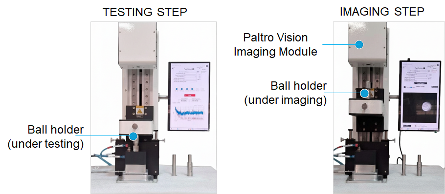
Inline imaging features a digital microscope that is built-in to the test unit for wear scar analysis, thereby eliminating requirement of separate microscope (Figure 3). The system is pre-configured to seamlessly transition to the imaging module on completion of the test (Figure 3).
Complete automation with digital modules not only improves productivity but these are crucial to enforcing and improving the repeatability and reproducibility in jet fuel lubricity evaluation. Some of the key automation capabilities include -
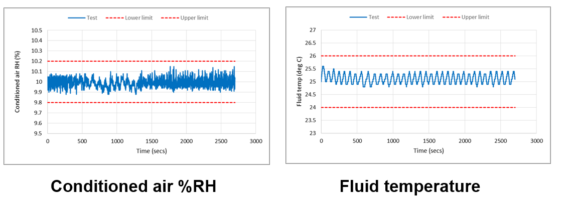
BOCLE-ADV is designed with closed-loop enclosures (Figure 1) with conditioned air flow and automated phase switching that is unaffected by ambient conditions and reduces volatility losses. Round robin programs have established that wear scar diameter is sensitive to %RH and its variation. Controlling this more accurately and implementing digital data logs (Figure 4) ensures lower variability and better traceability.
BOCLE-ADV features a unique hybrid automated loading system (Figure 3) that applies 1000 gm load (including ball, holder and all assemblies) on the ring at the start of the 30 min test phase. The motorized, impact-free system applies loads in a controlled manner every time ensuring consistent, repeatable results without manual intervention.
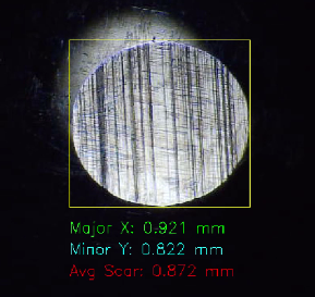
Auto-edge detect functionality powered by AI and ML algorithms precisely measures wear scar diameter without user dependency (Figure 5) and generates the test report.
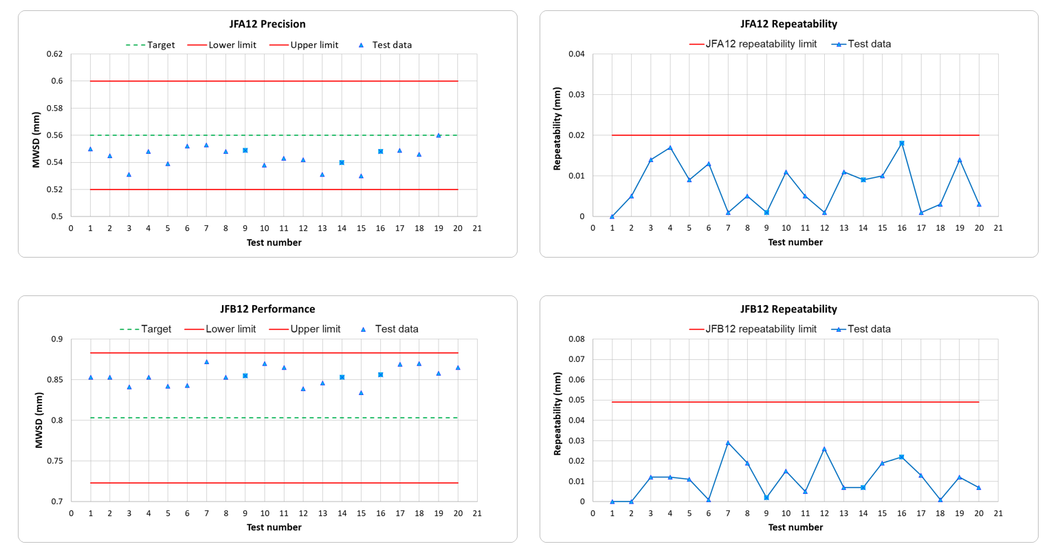
BOCLE-ADV is calibrated as per ASTM D5001 protocol (Link - Here) and validated (Figure 6) with both low and high lubricity reference fluids (JFA and JFB) that have defined acceptance limits based on the Certificate of Analysis from ASTM TMC. Furthermore, automated workflows with inbuilt pass/fail logs (Figure 7) creates a unique digital instrument record. Such records improve confidence and credibility of datasets generated on unknown fuels in intra-lab and inter-lab programs.

.svg)
.svg)
